2009 Corvette ZR1: Ruthless Pursuit of Power: Supercharged Edition - Page 3 of 7
 |
 |
Page 3 of 7
© 2008 by Hib Halverson
No use without permission, All Rights Reserved
![]() Discuss this article
Discuss this article
Another key advancement is the R2300's increased displacement over the largest production Gen 5, the M122. Eaton categorizes its blowers by the amount of air they move or "displace" during one rotation of the rotors. With the fifth gen series, the unit of measure was cubic inches (M122=122 cubic inches or 1999 cc.) With the TVS line, it's cubic centimeters (R2300=2300cc.) About 300cc more displacement and other enhancements has the R2300 flowing about 20% more air along with having a wider dynamic range than the M122. It builds boost more quickly at low rpm but can, also, sustain it at higher blower speeds, in this instance, 15,180 rpm at the engine's rev limit.
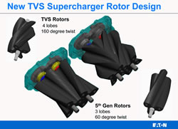
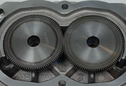
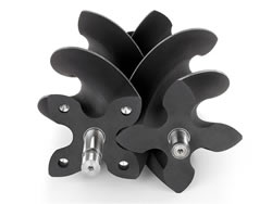
The next improvement was a switch from three to four lobe rotors and a significant increase of the rotor helix angle from the Gen 5's 60 degrees to 160 degrees. "Obviously, the thing you notice first is the four lobes and the higher twist," Yoon Lee said. "That allows you to do a better job of porting how the air gets to the rotors from the front of the unit. Once the air gets through the throttle body, then it has to get to the rotors through the supercharger intake. The tighter twist and the four lobes allow you to enlarge that opening which slows down the air.
"That's better than the fifth generation where there were cases of the air flow going sonic. It would speed up to get there but, as it went through the rotors, there was a fairly large reduction in air speed. That big a change in velocity affects how much power it takes to drive the unit as well as the amount of noise radiated through the case and out the throttle body."
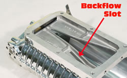
There was more work on efficiency and noise reduction at the supercharger outlet. "Backflow ports were added to the 3rd generation, primarily to quiet the sound of the supercharger," Eaton's Development chief, Mike Sitar states.
"Backflow is the method of compression within a Roots device. Air enters the inlet port, gets closed off by the rotor faces, then transfers from the inlet to the outlet at inlet pressure. As it hits the outlet port, if you didn't have backflow slots, the air would immediately rush backwards, through the outlet port, to bring that cavity up to outlet pressure, then the rotors would come into mesh and force the air back the other way, through the outlet. That's a full, air flow reversal in the outlet port.
"This reversal creates a high level of pulsation and noise. Backflow slots allow the air from the outlet to begin pressurizing that closed chamber before it moves to the outlet port. They allow air flow, into the supercharger, through those ports, then out the outlet port, maintaining one way flow through two different ports. We took a percent, maybe a percent and half hit in adiabatic efficiency, but it, also, allows a one to three decibel decrease in noise. It does impact efficiency of the supercharger, but our biggest goal was noise reduction.
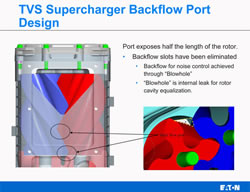
"The TVS does not have those backflow ports," Sitar continued. "Its backflow function depends on flow from the outlet to the rotor bore. There's actually a hole; we call it a "blowhole"; located within the rotor mesh. When the rotors mesh, there's still an open area that connects the rotors across the top of this cusp within the supercharger. In TVS, backflow occurs within the rotor set itself. The air is never moved to the discharge port, then brought back in.
"The blowhole exists continuously, it just moves forward all the time. It starts in the rear, after the inlet closes, and travels forward as the rotors mesh. It always exists between the rotors, but its position changes all the time.
"This allows our backflow event to be more than twice as long (than it was with the Gen 5), so before the rotor even opens to the outlet; the air is almost completely pressurized, inside the supercharger.
"The TVS still pressurizes the intake manifold through backflow, which defines it as a Roots device, but when it goes to the outlet port, it's primarily one way flow. The TVS is 5-10 decibels quieter, compared to a fifth generation supercharger and a lot of that is because of backflow management."
In fact, GM found that noise radiated by the supercharger case was reduced by 10-dBA. Building on the reduction in radiated noise, Eaton altered the acoustics of what was left, making it less noticeable. "The four lobes, also, change the frequency of the noise of this blower makes," Ron Meegan states, "so it doesn't have the same characteristic supercharger whine that you heard in some of the other applications. It still makes noise, but it's less objectionable because of the different (higher) frequency."
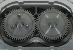
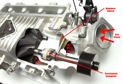
More noise reduction came from an increase in blower drive gear tooth count from 56 to 101 which raised the frequency of the gear noise to a less annoying level. Still more noise abatement comes from a blower drive shaft "torsional isolator", which isolates the supercharger from crankshaft speed variations which, at idle, if the isolator was not present, would cause "gear rattle".
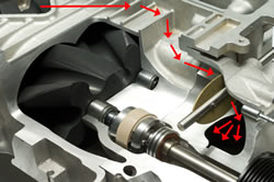
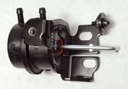
Some of the engine's power is used to drive the supercharger. Engineers call that "input power requirement" and limiting it is important to both fuel economy and the supercharger's ability to increase engine power. For better gas mileage, the Eaton blower has a bypass system, the core of which is a valve which allows some of the charge air to recirculate in the supercharger system during part-throttle, "unboosted" operation. A vacuum actuator operates this valve. When manifold absolute pressure drops below about 82 kPa (11.9 psi), this actuator opens the bypass and some intake air flows from the supercharger outlet, through the valve and back into the blower inlet. With the bypass open, the supercharger consumes only about half-a-horsepower which has minimal effect on fuel economy.
The same bypass valve is used to control boost at high engine speeds, but in that instance, pressure acting on the other side of the actuator opens the valve. The pressure is controlled by a solenoid operated by the LS9's engine control module (ECM). When boost reaches 10.5 psi, the ECM energizes the solenoid and the actuator opens the valve, venting manifold pressure to the blower intake and limiting boost.
Eaton, also, reduced the input power requirement when the blower is on boost. At the engine's power peak, it dropped from around 115 hp, for the Gen 5, to about 75-hp for TVS. This reduction came from the efficiency improvements cited earlier and efforts in friction reduction, chiefly with the rotor surfaces which mesh.
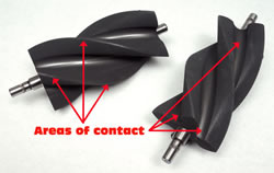
Rotor sealing is a double-edged sword. The tighter rotors mesh, the better they seal and the less leakage the blower sustains, however, a tight seal means more friction and more power used to turn the blower. Eaton maintains a tight seal, but reduces friction by: 1) holding tight tolerances during machining and final assembly, 2) treating the rotors with a graphite-based, abradable powder coating (APC). During the rotors' first few turns, part of this abrades away, leaving rotor lobe contact areas better matched to each other and able to run extremely close. That provides excellent sealing with minimal friction and 3) engineering the supercharger to be reliable and durable while sustaining outlet temperatures up to 300°F.
The four-lobe rotors, along with improving efficiency and reducing noise, made for a smaller rotor set which allowed a more narrow blower case. That, in turn, enabled the Eaton TVS to mount, lower, between the Gen 4 V8's heads. "One of the big things the Gen 6 did for us," Ron Meegan told the CAC, "was provide the (greater) output we needed in a smaller package than the Gen 5. That, along with the intercooler work that Yoon did, allowed us to package tight into the valley and get it under the hood of the Corvette."
The nature of supercharging is that, because it compresses air going into the engine, it adds heat to the charge air. Unfortunately, higher intake air temperature makes the engine more prone to detonation. The LS9 supercharger system attacks that problem on two fronts.
First, the efficiency improvements discussed previously, also, have the benefit of reducing temperature rise by 15% compared to the M122, so not only is the R2300 better performing, smaller and quieter, it's, also, adding less heat. "The same phenomena which reduces supercharger noise, also, accounts for the reduced temperature," Yoon Lee said. "With the Gen 6, air does not have to speed-up as much going into the rotor inlet and then immediately slow-down as it goes thru the rotors, so the air does not get as hot by the time it exits the supercharger discharge port."
Second, typical of many superchargers used in high-performance applications, both O.E. and aftermarket, the LS9 has an air-to-liquid, charge air cooler. Many, including its engineers, sometimes call this an "intercooler" but, if we're going to be dead-nuts accurate, it's a "charge air aftercooler" because it cools the intake charge after it exits the supercharger.
Whereas aftermarket C5/C6 Roots blower kits locate the cooler beneath the blower, the LS9 has the cooler above it. "The biggest consideration was packaging under the tight hoodline of the Corvette." Yoon Lee states, "If the supercharger was mounted on top, the pulley would have created a hood clearance problem because of the need to extend far enough forward to line-up with the accessory drive belt. When it comes to hood clearance, having the pulley sit high and forward is not as good as positioning it lower.
"We struggled a fair amount early-on with how to package everything. We were trying to balance how to cool this with the amount of room that we had. But, also, we were looking to minimize tradeoffs with combustion performance. Air-fuel distribution was one of the things we tried to minimize the impact on and, in this application, we went with dual intercoolers because, ultimately, that was the best packaging configuration for it to balance the pressure drop you had across the intercooler, coolant performance and the smallest packaging and it turns out that we didn't compromise the air-fuel and drivability by doing that."
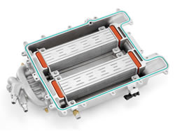
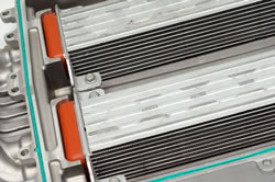
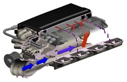
Inside the intake plenum, above the blower outlet, are two Behr heat exchangers; engineers call them "bricks". The Cadillac version of this system is a single brick system, but, on LS9, GMPT opted for a two-brick cooler because: the Corvette application has: 1) more air flow to cool and 2) a hood that's about an inch lower, so there was less space above the supercharger. Using two bricks reduced the required height yet offered the extra cooling. The intake air flows up, out of the blower, splits right and left, passes through and gives-off heat to the heat exchangers, then flows down, into the cylinder heads.
These coolers have a separate cooling system consisting of a radiator, about half the area of the engine's radiator, mounted at the front of the C6 cooling stack, an electric pump bolted to the right of the cooling stack, a reservoir on the left and associated plumbing. The system holds about a gallon of coolant—a water/Dexcool mix like that used by the engine cooling system—and is capable of cooling the intake charge up to 140 degrees. More importantly, the rapid temperature rise, typical of aftermarket and even some O.E. intercooled supercharger systems, during sustained, high load operation, does not occur with a ZR1.
Getting the function of the charge air cooler system right was a bit of a challenge. Corvette Chief Engineer, Tadge Juechter, told us that, early in the ZR1 development, the size of the radiator and the amount of coolant in the system were determined and then dynamometer testing and vehicle acceleration testing began. In those tests, results were good but, later, when sustained high-speed testing began in preparation for GM's brutal, "1 Tank/WOT" test, the Corvette Team encountered intake air temperature rise. Increasing the size of the charge air cooling radiator and adding coolant capacity were the eventual solutions.
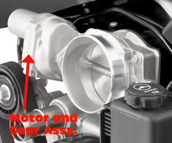
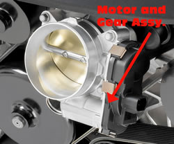
At the other end of the intake tract is the throttle body. The LS9 throttle bore is about a tenth of an inch smaller in diameter than what's used on LS3 or LS7. According to Ron Meegan, the slightly smaller bore costs about half a horsepower. "It's shared with some of our truck engines and is different," Yoon Lee told us. "LS3 uses an in-line throttle body with the motor off to the side. This one is a 'wraparound'—the motor is underneath the throttle bore and it's an 87 mm unit versus the LS3's 90.
"We found in testing that we could get the performance we need to meet our targets. The primary advantage of the wraparound is packaging—you reduce the overall height. We also found that the wraparound motor was more robust in terms of engine vibration because the motor isn't hanging out on the end (of the throttle shaft.) That wasn't an issue with the LS3, but this one is a little different. There's vibration coming from the engine through the blower case."
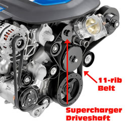
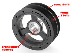
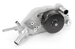
The blower drive system is another packaging accomplishment. Ideally, engine-driven superchargers have separate drive belts because of their load and, in fact, the LSA is configured that way. To get the LS9 into the C6, GM Powertrain had to get a little creative because there was not enough space at the front of the engine for three belts. The supercharger, the water pump and the power steering pump share the same belt, however, because of the blower's load, it's a wider, 11-rib unit. Also, to be reliable while loaded with up to 60 lbs/ft. torque by the supercharger, the harmonic damper/drive pulley assembly is both keyed to as well as being pressed on the crankshaft to prevent it from rotating on the crank snout. Because of the load and wider belt, the water pump bearing was upgraded to a larger size and a unique power steering bracket with large bearing and spline drive for the pump was designed. A second, normally-sized belt drives the air conditioning compressor and the AC generator.
 |
 |
